Analysis and experiment
Analysis(Induction heating simulation)
Visualizing high‑frequency induction heating to enhance quality from the prototyping stage.
Our company utilizes advanced simulation technology capable of reproducing high-frequency induction heating behavior on a computer. This allows us to optimize process conditions and improve quality from the earliest stages—well before actual production begins.
Through simulation, we can evaluate key parameters in advance, including temperature distribution within the workpiece, heat propagation, and current density. These analyses are performed based on factors such as coil geometry, operating frequency, and material properties. By predicting heating behavior beforehand, we can design highly efficient heating processes with minimal energy loss while reducing reliance on traditional trial-and-error methods and operator experience.
In particular, for applications such as the hardening of components with complex geometries—where physical prototyping can be difficult—simulation enables us to assess process feasibility in advance.
Furthermore, because the heating behavior can be visualized in an intuitive and easy-to-understand manner, customers who are new to induction heating can clearly grasp the process and proceed with confidence.
What Induction Heating Simulation Can Reveal
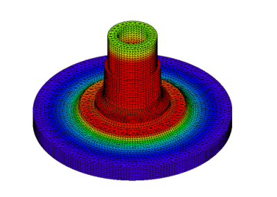
Induction heating simulation enables accurate prediction of temperature distribution and heat generation within the workpiece by taking into account coil design, heating conditions, and changes in material properties.
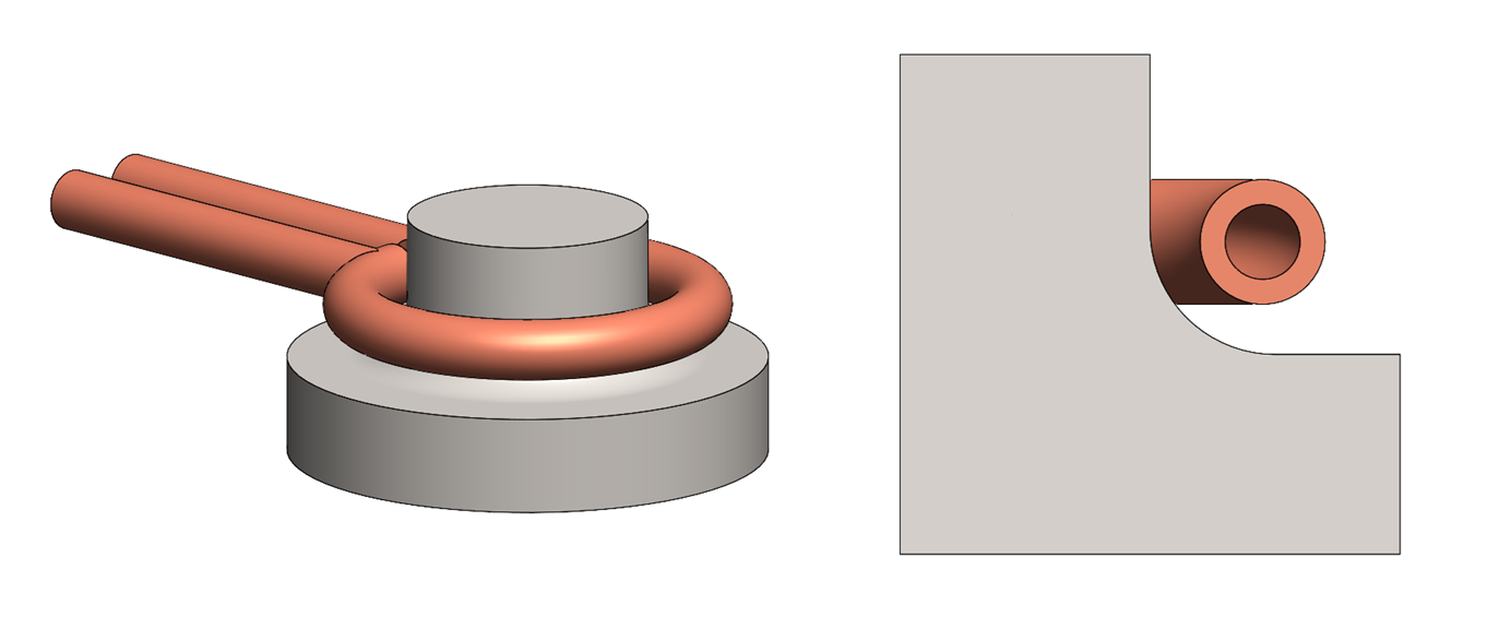
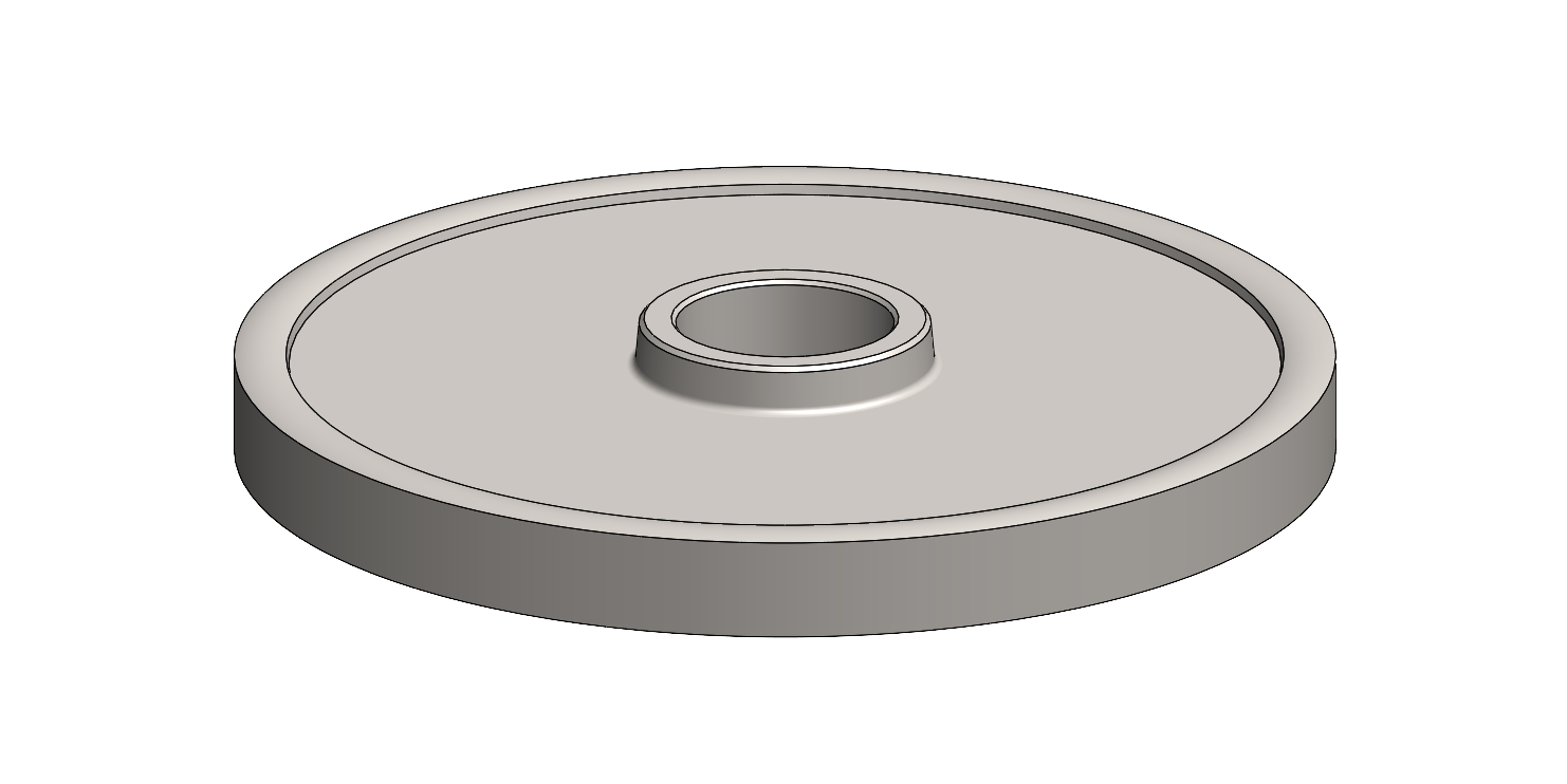
Figure 1: Analytical Model—Overall View (Left), Cross-Section (Right)
Case Study
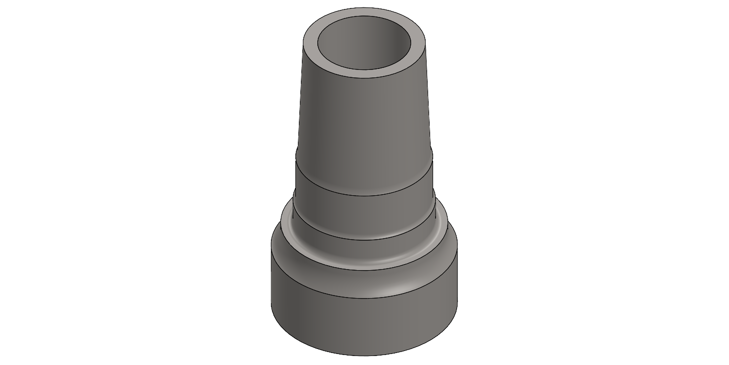
The analysis target is a carbon-steel shaft with an integrated flange.
High-frequency induction hardening is applied to improve wear resistance in the transition area between the shaft and the flange.
In this simulation, the operating frequency is set to 30 kHz.
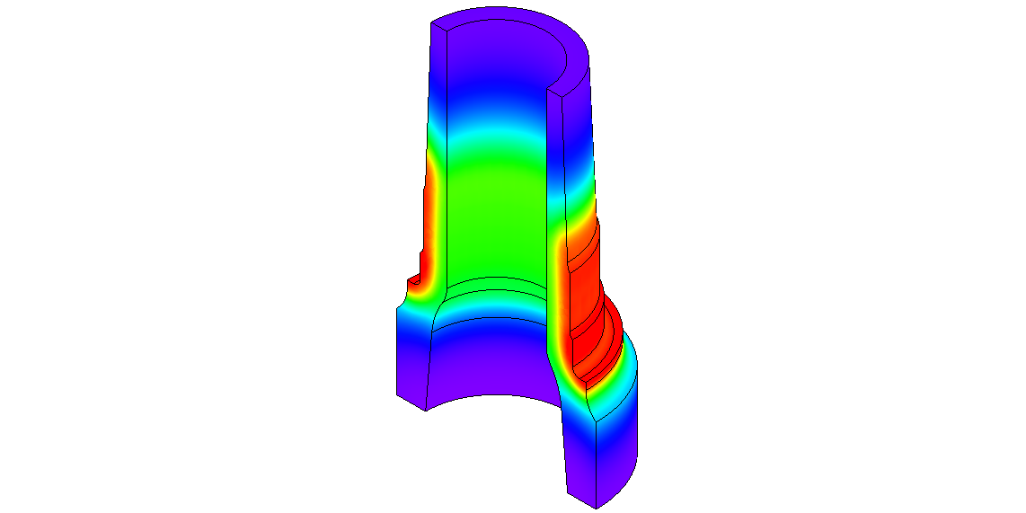
Time-Dependent Behavior
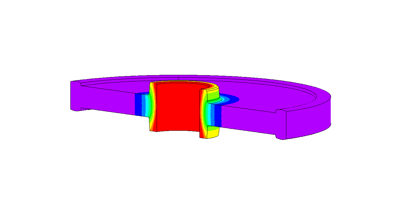
The analysis allows us to evaluate the temperature rise over time.
By examining the temperature distribution at each time step, we can visually observe where heating occurs and how heat propagates throughout the workpiece (Figure 2).
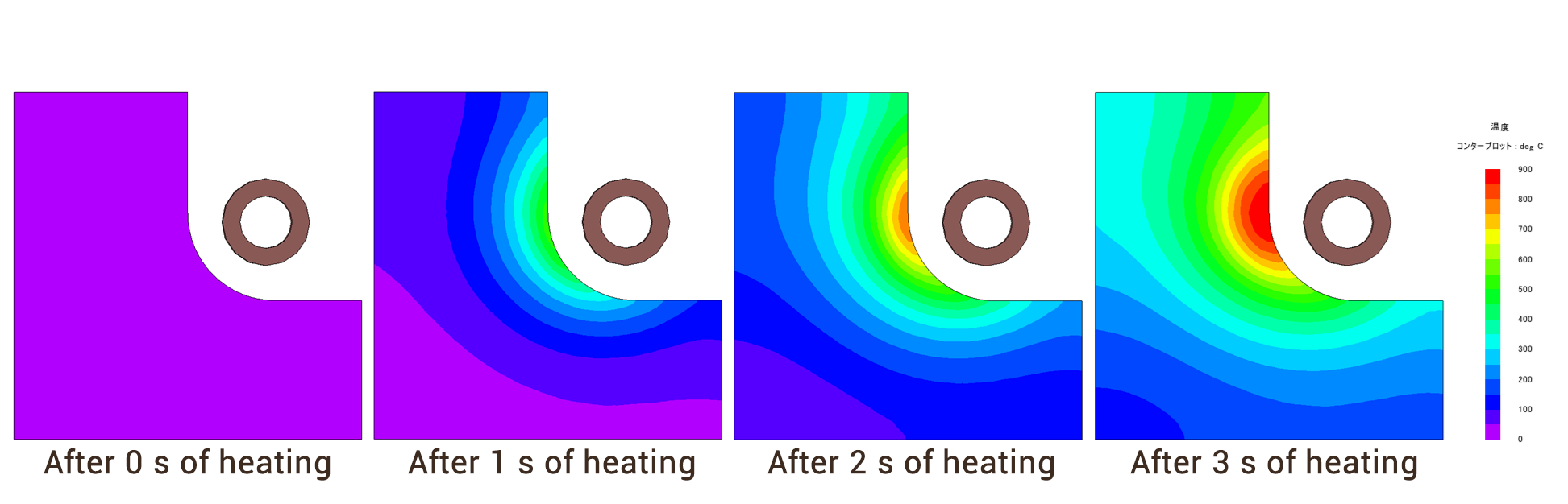
After 0 s of heating/After 1 s of heating/After 2 s of heating/After 3 s of heating
Figure 2. Temperature distribution after each heating duration (coil‑to‑shaft)
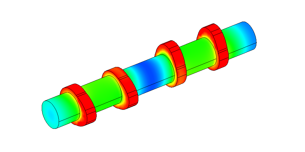
Impact of the Coil on Heating Behavior
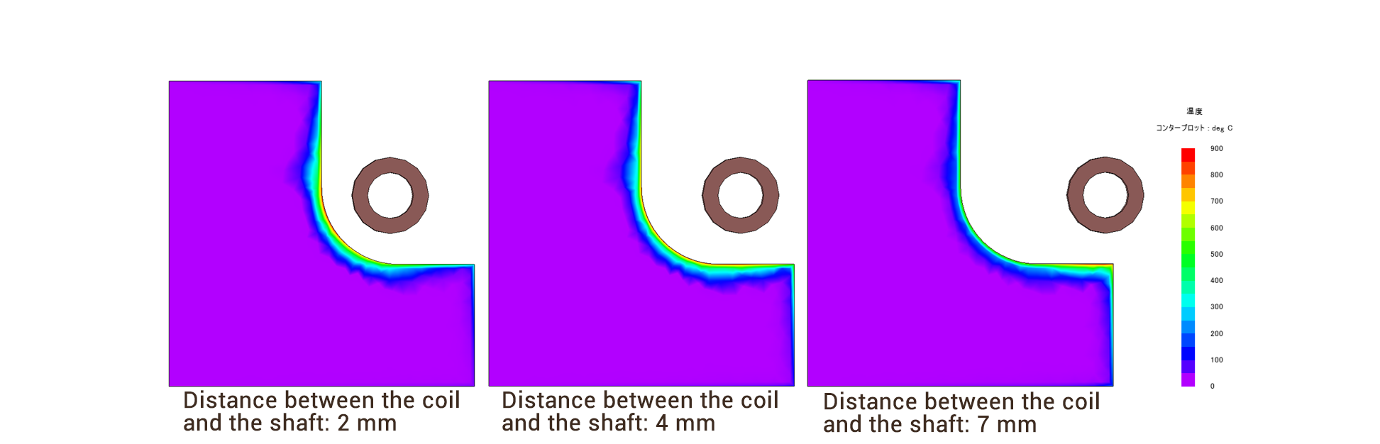
Changing the position of the heating coil alters both the location of maximum heating and the overall heating efficiency (Figure 3).
When the coil‑to‑shaft distance is 2 mm, the shaft side near the coil is sufficiently heated.
However, when the distance is increased to 4 mm, the amount of heat generated decreases, resulting in insufficient temperature rise. In addition, the temperature distribution shifts, with heat spreading more toward the flange side.
When the coil‑to‑shaft distance is further increased to 7 mm, the heating pattern changes significantly. The region experiencing the strongest heating moves away from the shaft side, and the flange edge becomes the area of highest temperature.
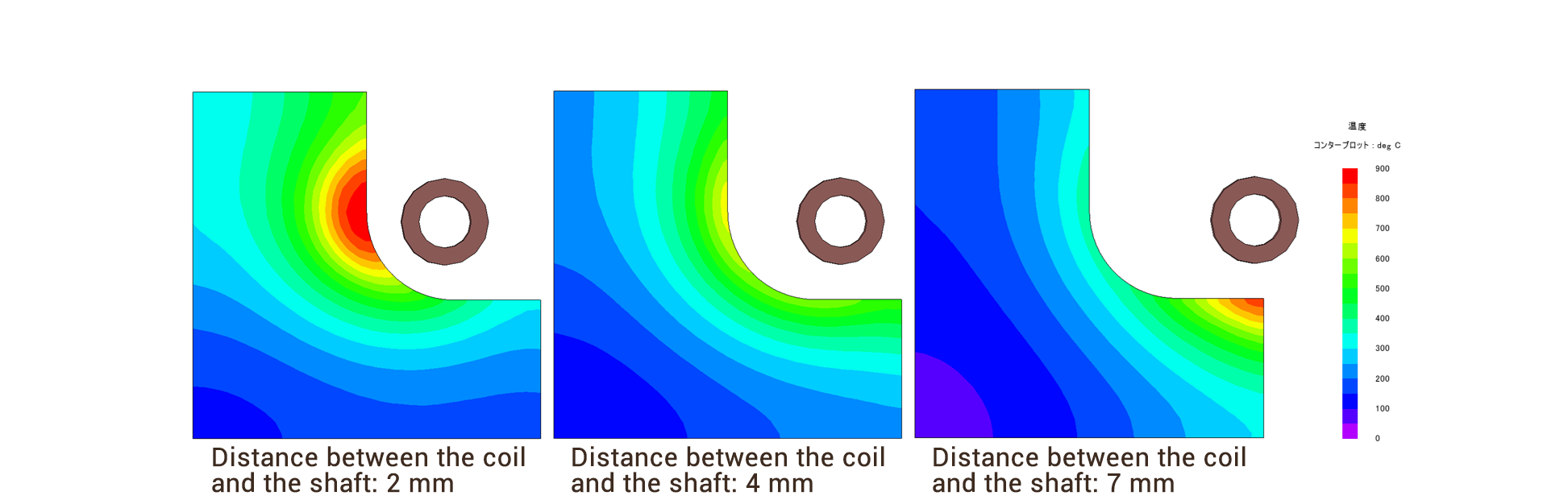
Figure 3: Temperature distribution when the distance between the coil and the shaft is varied (heating time: 3 seconds)
Although the heat generation decreased when the coil‑to‑shaft distance was set to 4 mm, increasing the input current makes it possible to raise the temperature sufficiently over a wider area (Figure 4).
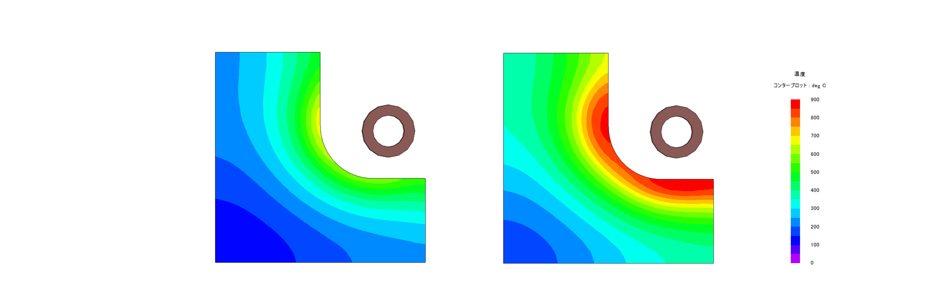
Figure 4. Differences in temperature distribution depending on input current
(Left: Low input current / Right: High input current)
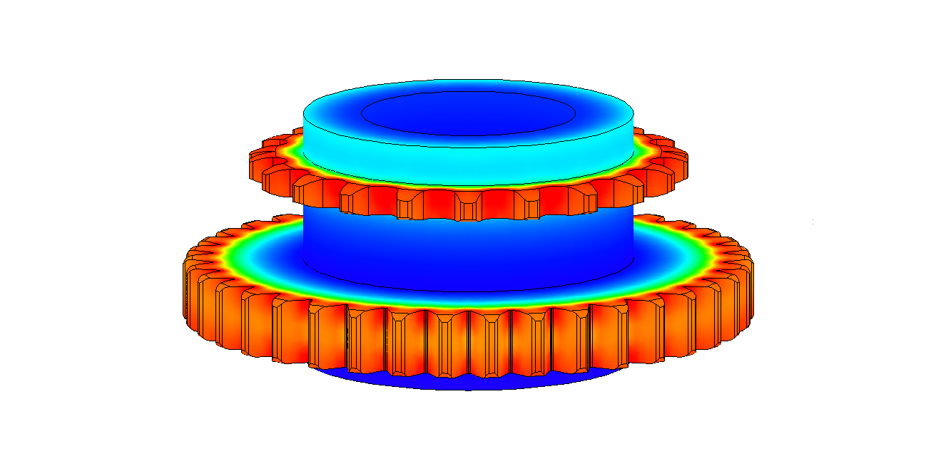
The heating behavior changes not only with coil‑to‑shaft distance but also with coil geometry.As the coil pipe diameter increases, both the location of maximum heating and the overall heating efficiency vary (Figure 5).
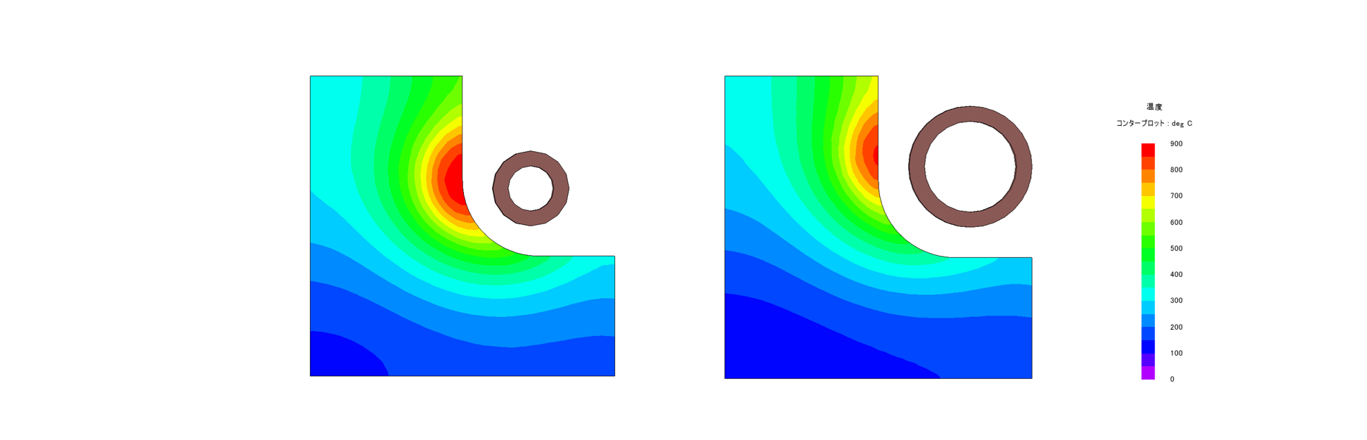
Figure 5. Differences in temperature distribution depending on coil pipe diameter
(Left: Small pipe diameter / Right: Large pipe diameter)
Visualizing the Invisible
Through simulation, we can evaluate where eddy currents are generated within the workpiece and how current flows through the heating coil.
By analyzing the current distribution, it becomes possible to assess the appropriateness of the coil position and geometry, as well as to examine potential design modifications.
In the previous case study, where the coil‑to‑shaft distance was varied, the results show that a shorter distance induces stronger eddy currents on the shaft side.
To increase the overall surface temperature, including the flange, it is more effective to position the heating coil slightly farther away from the workpiece (Figure 6).
However, increasing the distance reduces the amount of heat generated, which means that higher input power is required to achieve the same heating effect.
Coil‑to‑shaft distance: 2 mm/Coil‑to‑shaft distance: 4 mm/Coil‑to‑shaft distance: 7 mm
Figure 6. Current density distribution for different coil‑to‑shaft distances
In addition to the information described above, it is also possible to incorporate factors such as operating frequency, material properties, the influence of fixtures, as well as conditions involving rotation or scanning (traveling) heating into the simulation for further evaluation.
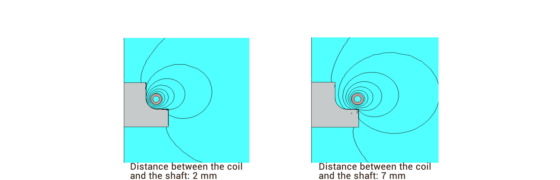
Coil‑to‑shaft distance: 2 mm/Coil‑to‑shaft distance: 7 mm
Figure 7. Magnetic flux lines for different coil‑to‑shaft distances
Experiment

Meeting Customer Needs with Innovative Solutions
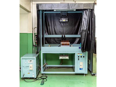
Our laboratory is equipped with high-frequency induction heating test machines to meet a wide range of customer requirements.
We conduct a variety of heating tests, including quenching, tempering, and more.Leveraging decades of expertise, we provide optimal heat treatment solutions tailored to your needs.
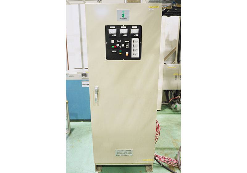
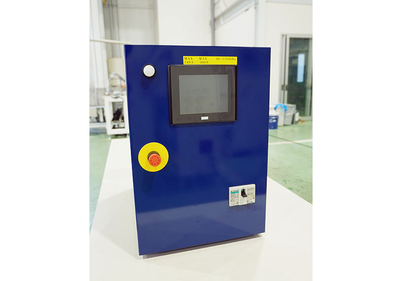
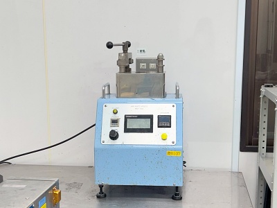
Test Equipment
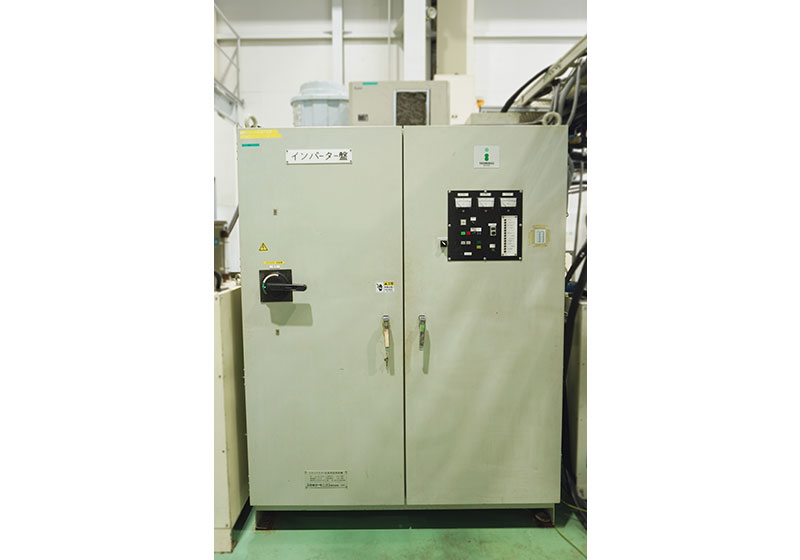
TRANSISTER TYPE OSCILLATOR
{Spec}
Output:Max30kW/Frequency:3kHz~100kHz
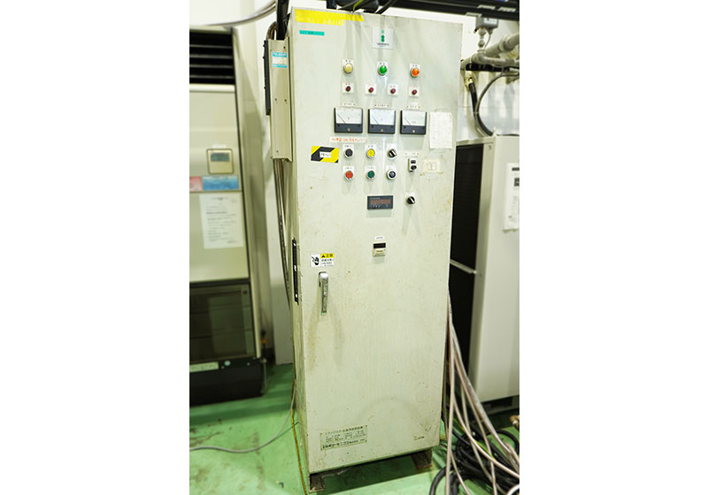
TRANSISTER TYPE OSCILLATOR
{Spec}
Output:Max100kW/Frequency:3kHz~100kHz
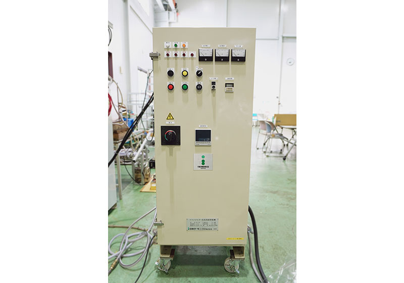
TRANSISTER TYPE OSCILLATOR
{Spec}
Output:Max50kW/Frequency:3kHz~100kHz
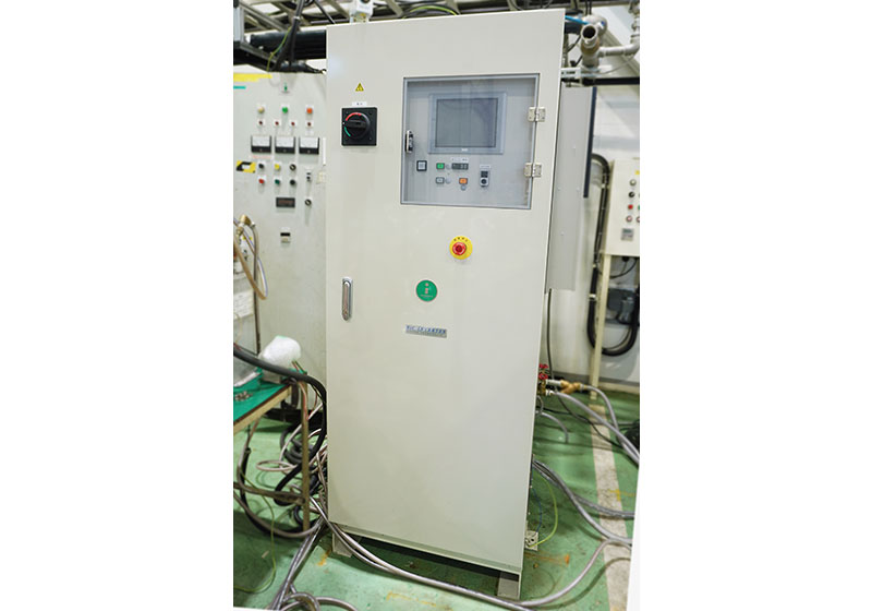
TRANSISTER TYPE OSCILLATOR
{Spec}
Output:Max10kW/Frequency:3kHz~100kHz
TRANSISTER(SiC)TYPE OSCILLATOR
{Spec}
Output:Max50kW/Frequency:100kHz~200kHz
TRANSISTER(SiC)TYPE OSCILLATOR
{Spec}
Output:Max5kW/Frequency:100kHz~200kHz
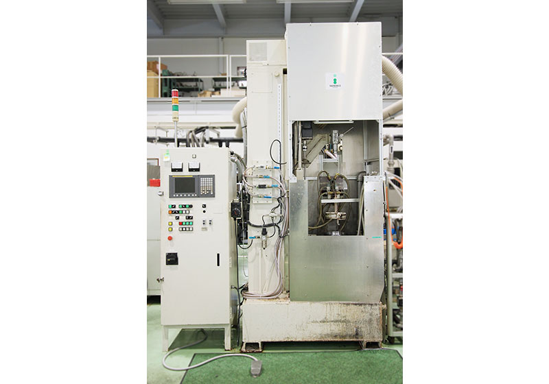
Vertical NC-controlled Machine
{Spec}
Max stroke:900mm
Single axis
Max Speed:200mm/sec
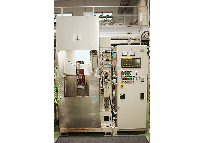
Vertical NC-controlled Machine
{Spec}
Max stroke:500mm
Single Axis
Max Speed:200mm/sec
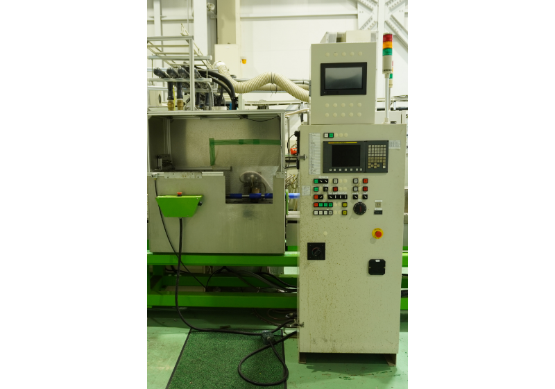
Horizontal NC-controlled Machine
{Spec}
Max stroke:500mm
Single Axis
Max Speed:200mm/sec
Inspection Equipment
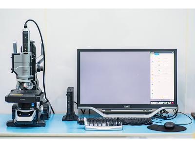
Digital Microscope
A device for metallographic observation of heat-treated workpieces.
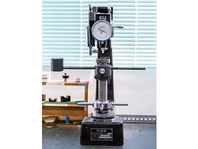
Rockwell Hardness Tester
A device for measuring hardness after heat treatment.
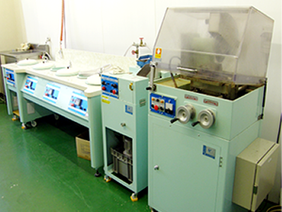
Sample Preparation Machine
A device for cutting and polishing workpieces.
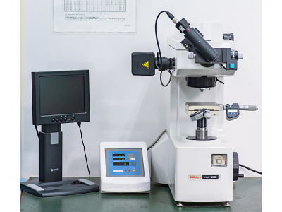
Micro Vickers Hardness Tester
A device for measuring hardness after heat treatment.
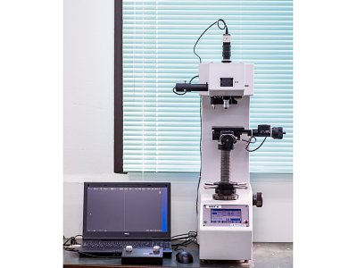
Vickers Hardness Testing Machines
A device for measuring hardness after heat treatment.
Resin Mold Machine
Magnetic Particle Inspection Machine
Equipment for detecting cracks on the material surface.
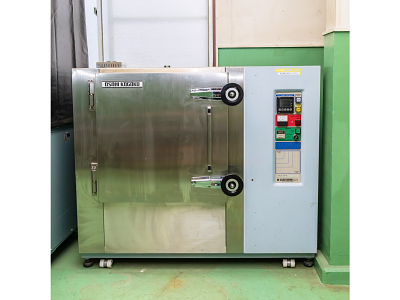
Electric Furnace
Used for processes such as tempering, available 0–600 ℃.
Prototyping Examples
Quenching/Tempering
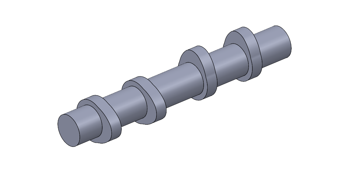
Drive shafts, Crankshafts, Camshafts, and Armature shafts
Shrink Fitting
Motor housing, Motor shafts
Brazing
Various tool tip brazing and Soldering
Heating
Pipe Sintering, High-temperature Material Property Testing, and Heating of Metal and Carbon Crucibles
Supports NC-controlled progressive hardening and single-shot methods.
Fully programmable NC control for complex hardening processes.
We also provide comprehensive inspection equipment for quality checks.
To accommodate diverse prototyping and testing needs, we maintain a wide range of heating coils.
If an appropriate coil is not available in our inventory, we can manufacture custom coils at our coil processing facility.
Contact
We welcome your inquiries via our contact form or by phone.